Erosion Thickness Readme
GUI Workflow
ET GUI program contains three tabs: file, visualization, and skeletonization. A general work flow starts from importing input files, computes ET, MC, and skeletons under skeletonization, and interactive visualization through controls in both visualization and skeleton tabs.
-
Preparing input: One way to obtain medial axis and radius files for a triangular surface mesh is using our VoxelCore method
-
Import input files: The medial axis mesh file (
.ply) and the.rfile that defines distance to the shape surface are required. A shape mesh (.obj) can be optionally provided for visualization purpose. Click buttonloadto load and render the meshes, which enables the visualization sections for surface and MA (highlighted in orange). In this example, MA and R were computed by VoxelCore for the shape of bunny. VoxelCore also generates a voxelized shape which is used here for surface visualization.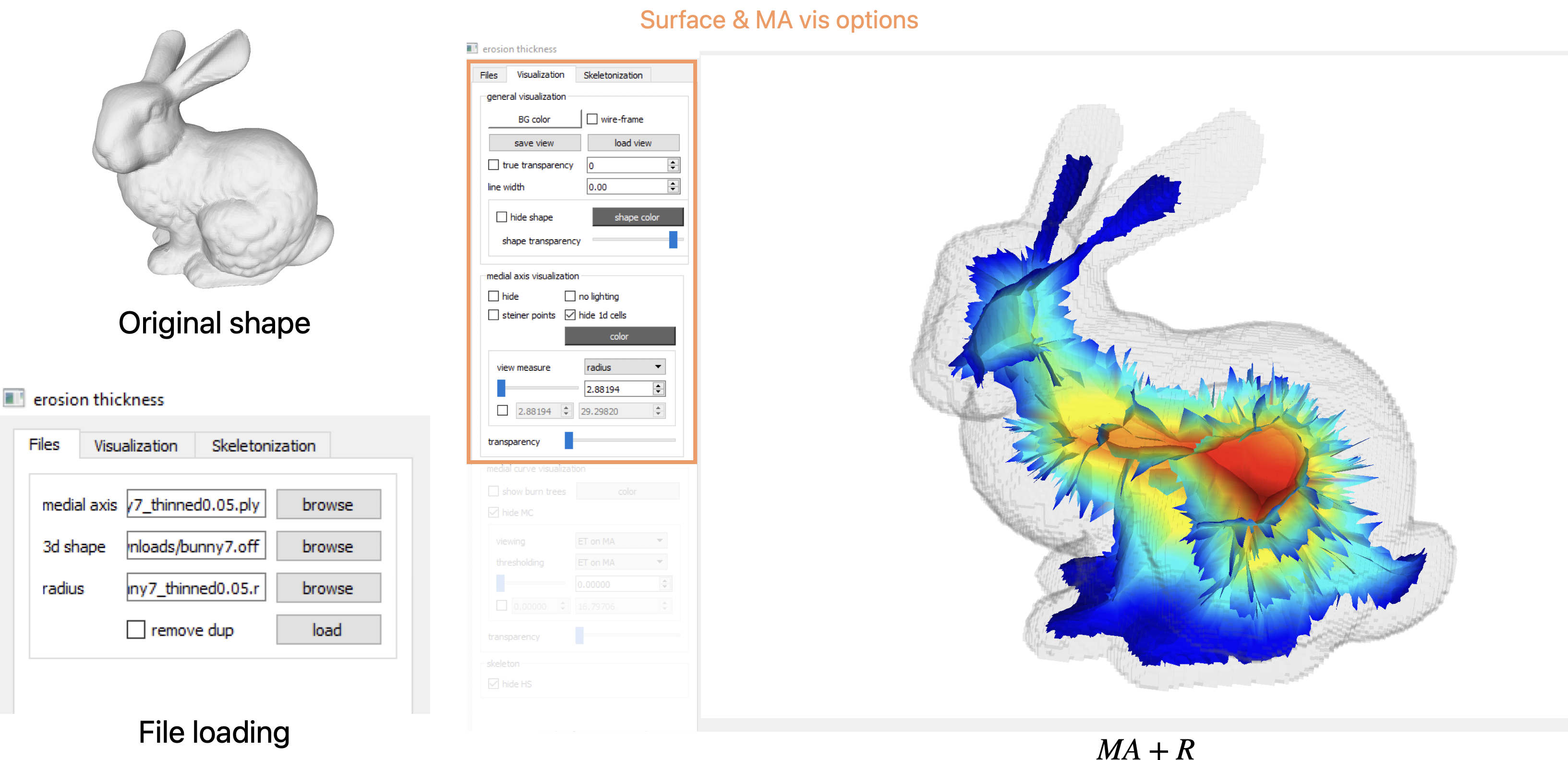
Providing input files to ET program. MA colored by radius field is visualized. -
Computing skeletons: Next, go to
Skeletonizationand clickprecomputeto computes all the measures used for generation of skeletons. Once finished, sliders are enabled to set thresholds for $ET_M$ and $ET_C$ to keep a subset of surfaces and curves above the thresholds. Clickcreateto visualize the subsets. Finally, createexportto write the resulting skeleton to a.skelfile. In the figure two sample skeletons are shown with their thresholding values shown in the UI.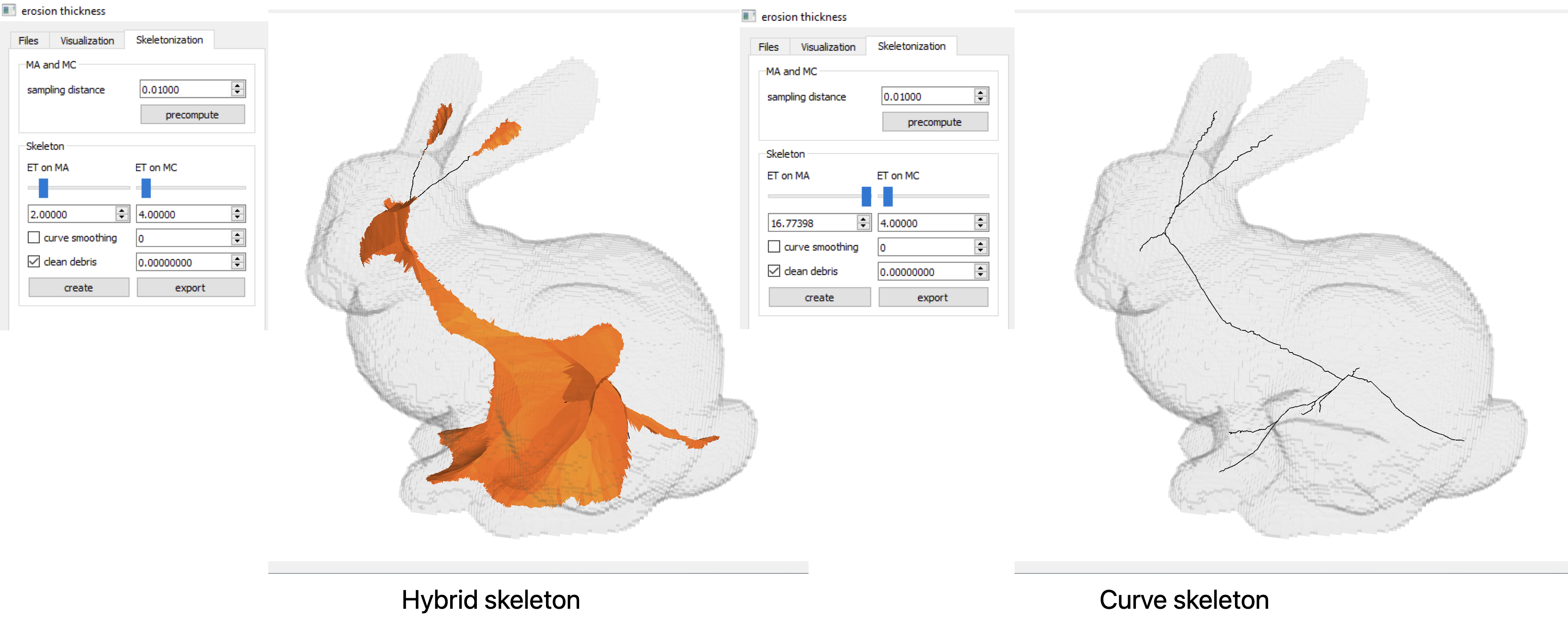
Two sample skeletons and their corresponding thresholds. -
Measures visualization: All measures have been computed at this point, and can be rendered using controls in
Visualization. Below we show two example measures, i.e. $ET_M$ and $ET_C$ on MA and MC respectively. These can be changed in the dropdown list of MA and MC visualizaion sections.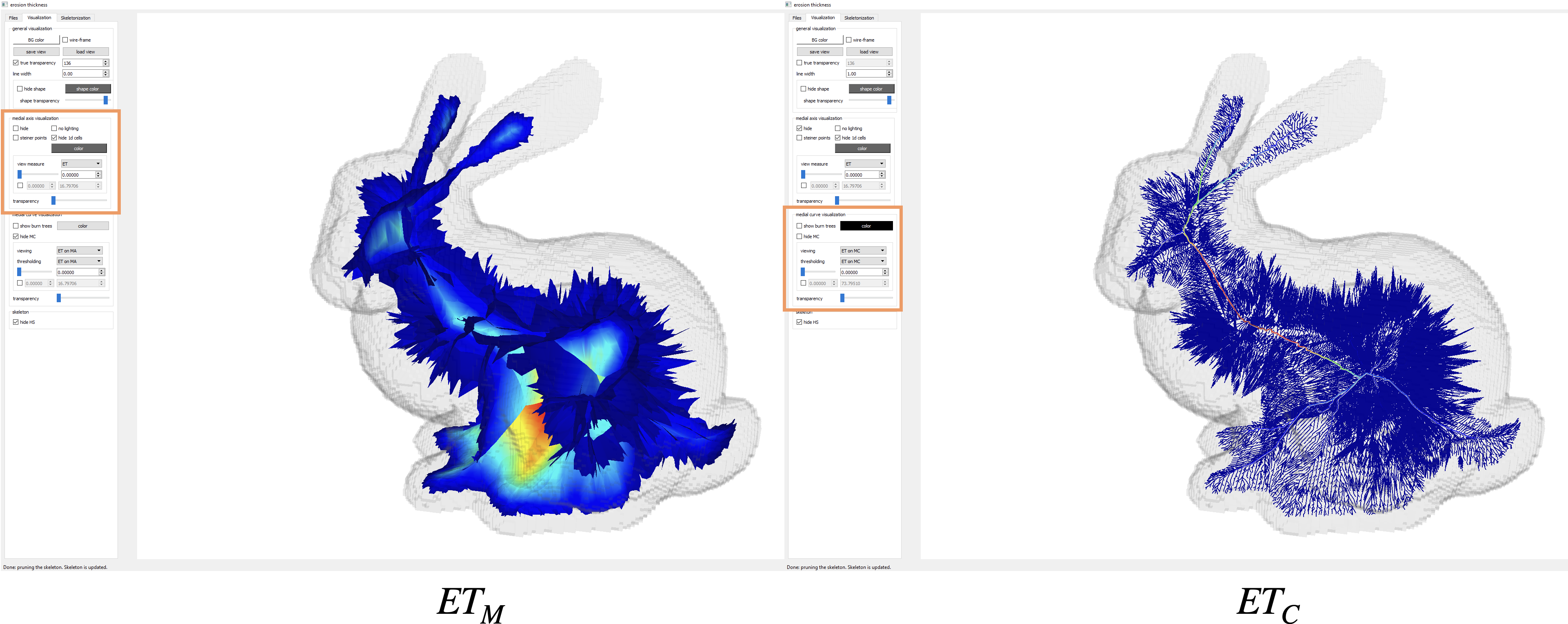
MA and MC are colored by $ET_M$ and $ET_C$ respectively.
Command-line Arguments
Enter non-graphical mode using --nogui when calling the exe from terminal. Arguments can be printed by feeding --help to the exe. They are defined in the main.cpp file. We use gflags to process command lines args. In general we recommend using --opt value if opt accepts a value, or --opt if opt is a boolean type that turns on/off some feature. See https://gflags.github.io/gflags/#commandline for more on the general intended use.
-
--nogui, type: bool default:false, “use cmd line instead? OPTIONAL.” -
--shape_file, type: str default:"", “the file for the 3d shape boundary. OPTIONAL.” -
--ma_file, type: str default:"", “the file for the medial axis. REQUIRED.” -
--r_file, type: str default:"", “the file for the radius function over medial axis. OPTIONAL.” -
--export_skel, type: bool default:false, “compute all the way to curve skeleton generation & output skel files.” -
--runall, type: bool default:false, “compute all the way to skeleton generation.” -
--omega, type: float default:0.01, “the sampling rate for steiner subdivision. OPTIONAL.” -
--burn_sch, type: int default:1, “the burning scheme (0: orig-and-steiner, 1: steiner-only(default value)). OPTIONAL.” -
--mc_msure, type: str default:"null", “output specified measure on medial curves. nothing to output by default. valid value: {shape-diam,shape-width, …}. OPTIONAL.” -
--theta_2, type: float default:1.1, “skeleton threshold for face pruning. Assume unit bounding box. All faces purged when > 1. OPTIONAL.” -
--theta_1, type: float default:0.05, “skeleton threshold for curve pruning. Assume unit bounding box. All curves purged when > 1. OPTIONAL.” -
--smooth_i, type: int default:0, “# smooth iterations for skel curves. OPTIONAL.”